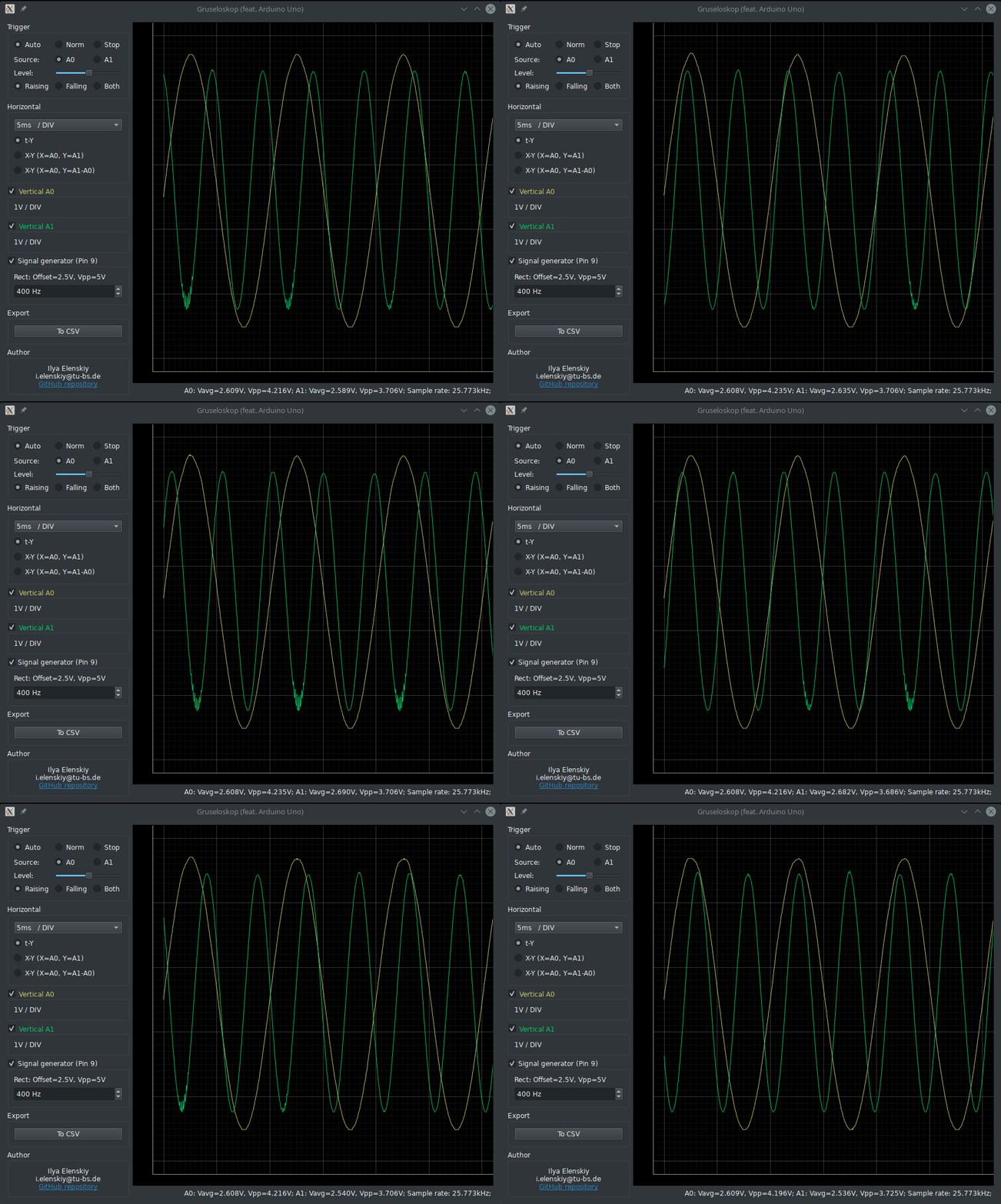
Gruseloskop (german worldplay refering to the idea of having this as the only tool in your lab) is a simple oscilloscope GUI for Arduino Uno.
Companion Arduino Uno sketch must be manually flashed using Arduino IDE You can find the sketch under firmware.
This is a project hacked together over a weekend and is not regularly maintained. Keep bleach closely available at all times to wash you eyes in case you accidentally see the source code. Consider yourself lucky if you find a comment there.
First, ensure that Qt is installed using your distribution's package manager.
Use pip to install the GUI, note that it will automatically install PySide2
Qt bindings.
pip install git+https://github.com/EvilMav/gruseloskop.gitUnless you have python installed, you can grab a latest stand-alone binary package,
named something like gruseloskop-x.x.x-amd64.zip, under
releases. It contains an .msi installer and the compatible Arduino
project. After running the install, you can run Gruseloskop using the Desktop or
Start-Menu shortcut.
Do not be too surprised about the big size of the installer: it contains a large part of a Python/Qt distribution to make your life easier.
Connect you Arduino Uno and use the IDE to compile and install the firmware.
When using windows package, the right firmware is included with the downloaded archive.
TimerOne library must be installed for this to compile, which can be done in the IDE
using Sketch->Include Library->Manage Libraries... menu.
Simply launch gruseloskop from the command line (or doubleclick gruseloskop.exe
on Windows) with Arduino connected. It will automatically detect the correct serial
port by the currently hardcoded VID:PID pair.
Currently, selectable edge triggers are supported. After each trigger, the arduino will
sample A0 and A1 channels with 8 bit, filling 800 sample buffer. The sample rate is
chosen such that at least one screen of the GUI is filled, achieving a maximum of about
38.4kHz at sufficiently low time bases. Pin 9 can be used as a 5V rectangle wave
generator output with selectable frequency between 1Hz and 5kHz.
Be careful with the voltages: to achieve a 5V input range the Vcc of the Board is used as the reference voltage. When connected to USB only, this is subject to an USB supply tolerance of up to 10%! When connected to an external supply, the on-board linear regulator will likely provide more reproducible results, so use it when possible.
Feel free to fork and submit pull requests. Any python code checked in must be formated using Black, which forces PEP8 but with 88 columns rather then 80.
For a development install use
python setup.py developinside the checked-out package directory. Rebuilding windows .msi is done using
python cx_setup.py bdist_msiunder a running windows install.

